A10-C Standby Compass: Final Setup
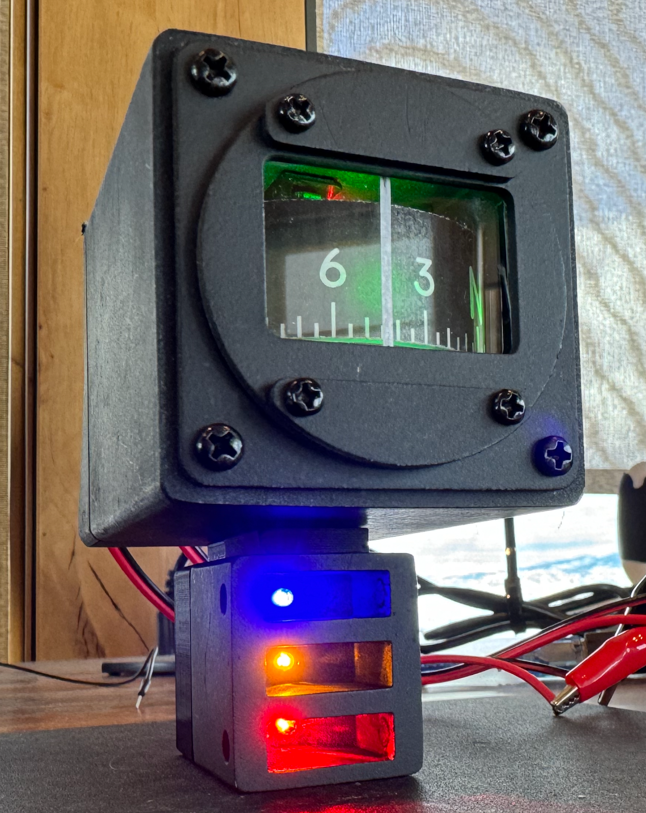
Got everything soldered together (after likely damaging one EasyDriver and moving to a backup) and squeezed it into the case. At first I thought the compass wheel was much too high but then I realized the front bezel was installed upside down.
Used an Exacto knife to cut a piece of acrylic for the front glass and put a small vertical sticker on it to act as the reference line. Not super pretty but works ok until I can cut with a laser instead (maybe an xTool).
Getting everything to fit was trickier than I expected, but it all worked out without too much rework required. I used some 5.5mm x 2.1mm plugs for the 12v power plugs (tip/center was positive).
For the aerial refueling LEDs I used some more LEDs that have resistors built-in. They are made for 12v so will likely bit a little dim since I am powering them off the digital out 5v pins from the Nano. Don't have a way to make the lens for those yet so will wait to see if that is the case. So far so good though!
Since I had about 8 wires routed out of the compass box, once it was all setup, I lost track of which wire was which. Had to pull the guts out again and zip tie groups of wires before reinstalling things. Haven't found a good way to label these tiny 22AWG wires yet.
Designed a 3D printed back cover for the AR LEDs (in Fusion 360).