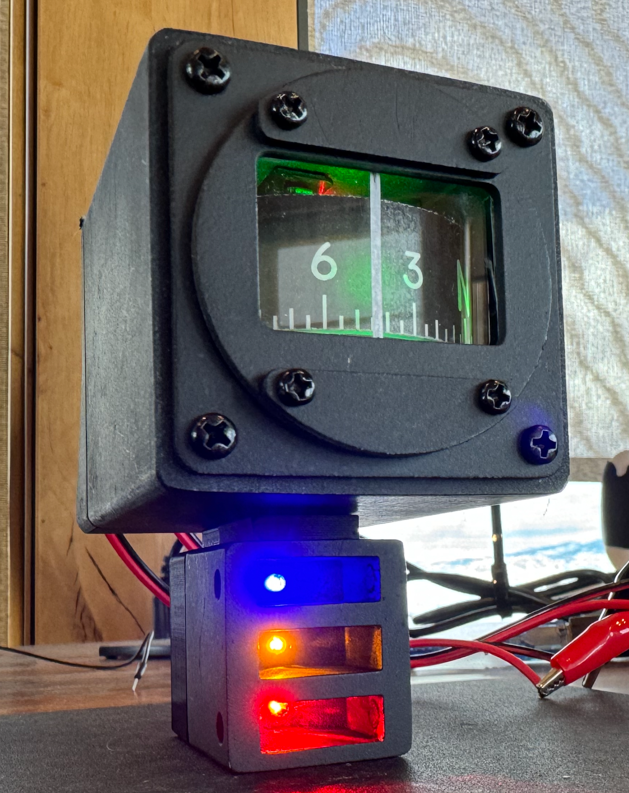
A-10C Standby Compass - Hardware Wiring
Components:
- Arduino Nano, no headers attached
- EasyDriver board to run stepper motor
- 2x 12V power circuits (for LEDs and motor power) - used computer power supply with ATX breakout board
- IR sensor
- X27 168 Stepper Motor
- 3 green LEDs with built-in resistor
- 3 LEDs for the Ready/Latch/Disconnect box (and resistors if not built in)
- 3D printed parts from The Warthog Project
Wiring
- 3 green LEDs, in parallel -> power and ground to one 12V circuit
- Arduino Nano (10 connections, plus USB)
- D11 to IR Sensor "OUT"
- D3 to EasyDriver DIR
- D2 to EasyDriver STEP
- GND to IR sensor GND
- GND to EasyDriver control GND (by STEP)
- 5V PWR to IR Sensor VCC
- D6, D7, D8 and ICSP GND (from the 6-pin cluster) routed out of box to later power the 3 LEDs below this compass unit ("ready", "latch", "disconnect")
- IR Sensor (3 connections)
- VCC to Nano 5V
- GND to Nano GND
- OUT to Nano D9
- Stepper Motor (open it to remove tiny plastic stop tab, for 360 motion - 4 connections)
- Coil 1/A wires to EasyDriver A+ and A-
- Coil 2/B wires to EasyDriver B+ and B-
- No polarity on coils but if things run backwards you can fix in the Arduino code
- EasyDriver (9 connections)
- M+ PWR In to second 12V power circuit
- GND beside M+ to ground on second 12v power
- MOTOR section (4 pins):
- A pair to one coil on Stepper
- B pair to the other coil
- STEP section
- GND to Nano GND
- STEP to Nano D2
- DIR to Nano D3