A-10C Standby Compass: Basic Functions Working
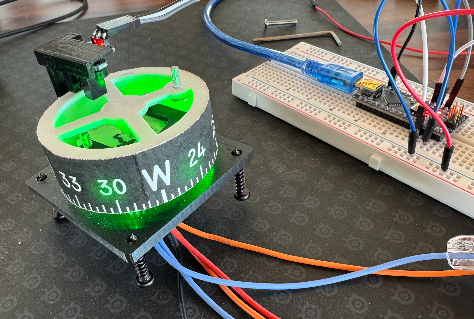
After getting the stepper motor to move yesterday I worked on the LEDs and getting the IR sensor into the mix today. My LEDs are green ones that have the resistor built-in, and therefore are expected to be wired to my 12v power supply in parallel. That generally went ok even with my sub-par soldering skills but there was very little room for things. If I had made my own 3D print for the LED holder (or had the original 3D design files) I might have improved that a bit, but I made it work.
Here's the code I used for this today.
Things I learned while copying this awesome work:
- Be careful with how wires need to route before putting heat-shrink on them, that stuff doesn't bend well. Also consider the type of wire in use: I switched to easy bending wire for the things I had to route around tight spots.
- If the motor spins the wrong way, swap the pins on ONE of the coils, A or B - or use the AccelStepper's setPinsInverted() function in the Arduino code to invert the DIR pin instead.
- My stepper seems to skip sometimes when doing its startup calibration to find the nail with the IR sensor. Seems to work ok with DCS though, so hopefully nothing is wrong. I played with the current limiting potentiometer on the EasyDriver but that didn't seem to help much. Left it in the middle setting (the silk screening showing which way adds current may be backwards so be aware). This improved when I went with the 1/8 step mode that the EasyDriver defaults to.
- My EasyDriver board requires MS1 and MS2 be grounded to get full-step action. Before I did that the motor turned way too slow and would not align with the heading data from DCS. I ended up NOT grounding those and just setting my max-step count 8 times higher. Was better that way.
- Sizing that nail for the IR sensor was a bit tricky because I had to pretty much assemble the core parts to take a measurement - still got it wrong the first try.
- I ended up using thick CA glue to glue the nail in and to attach the IR sensor to it's holder. Hopefully that will hold up.
- I also carefully used some of that same CA glue to provide a better friction fit for the main wheel that sits on the motor. My 3D print made the hole way too small, and unfortunately I did not have a perfectly sized drill bit for my pin vice - so I oversized it a bit and then used CA glue to fill in back in. I used a spare motor's drive shaft to keep the hole clear while the fresh glue setup - moved the motor in and out of the wheel center hole to keep it from getting glued in. Very fussy.
- I could only get one screw in to secure the 3D printed IR holder to the unit. I may use some glue if need be, but likely not required.
- The accuracy seems to be with 5 degrees of the real data. Maybe that would be better with a thinner nail (or other obstruction) for the IR sensor to calibrate against. That did improve when I changed to embrace the default 1/8 step mode from the EasyDriver.