I went through the SimCom training, which was a ton of fun, and reached the mentor hours required by my insurance, so it was SOLO time! I did a quick lap in the local area and captured parts of it on video.
Components: Arduino Nano , no headers attached EasyDriver board to run stepper motor 2x 12V power circuits (for LEDs and motor power) - used computer power supply with ATX breakout board IR sensor X27 168 Stepper Motor 3 green LEDs with built-in resistor 3 LEDs for the Ready/Latch/Disconnect box (and resistors if not built in) 3D printed parts from The Warthog Project Wiring 3 green LEDs , in parallel -> power and ground to one 12V circuit Arduino Nano (10 connections, plus USB) D11 to IR Sensor "OUT" D3 to EasyDriver DIR D2 to EasyDriver STEP GND to IR sensor GND GND to EasyDriver control GND (by STEP) 5V PWR to IR Sensor VCC D6 , D7 , D8 and ICSP GND (from the 6-pin cluster) routed out of box to later power the 3 LEDs below this compass unit ("ready", "latch", "disconnect") IR Sensor (3 connections) VCC to Nano 5V GND to Nano GND OUT to Nano D9 Stepper Motor (open it to remove tiny plastic stop tab, for 360 motion - 4 connections) Coil 1/A...
One of the final items to add to this instrument build (besides the text covers for the lower LEDs) was the sun shade for the AR LED box. I made this out of thin aluminum sheets , cutting it from a template using some metal sheers . My template was created by tracing some of the actual artwork from the DCS sim, and then scaling it to the proper size. It turned out ok, not perfect but pretty good. Primed and painted it and then installed it using 2 of the 4 holes that were already on the LED box 3D print. I used some heat inserts in those holes to give the screws something to bite, but the holes are really too big for my inserts so had to use some glue to help out.
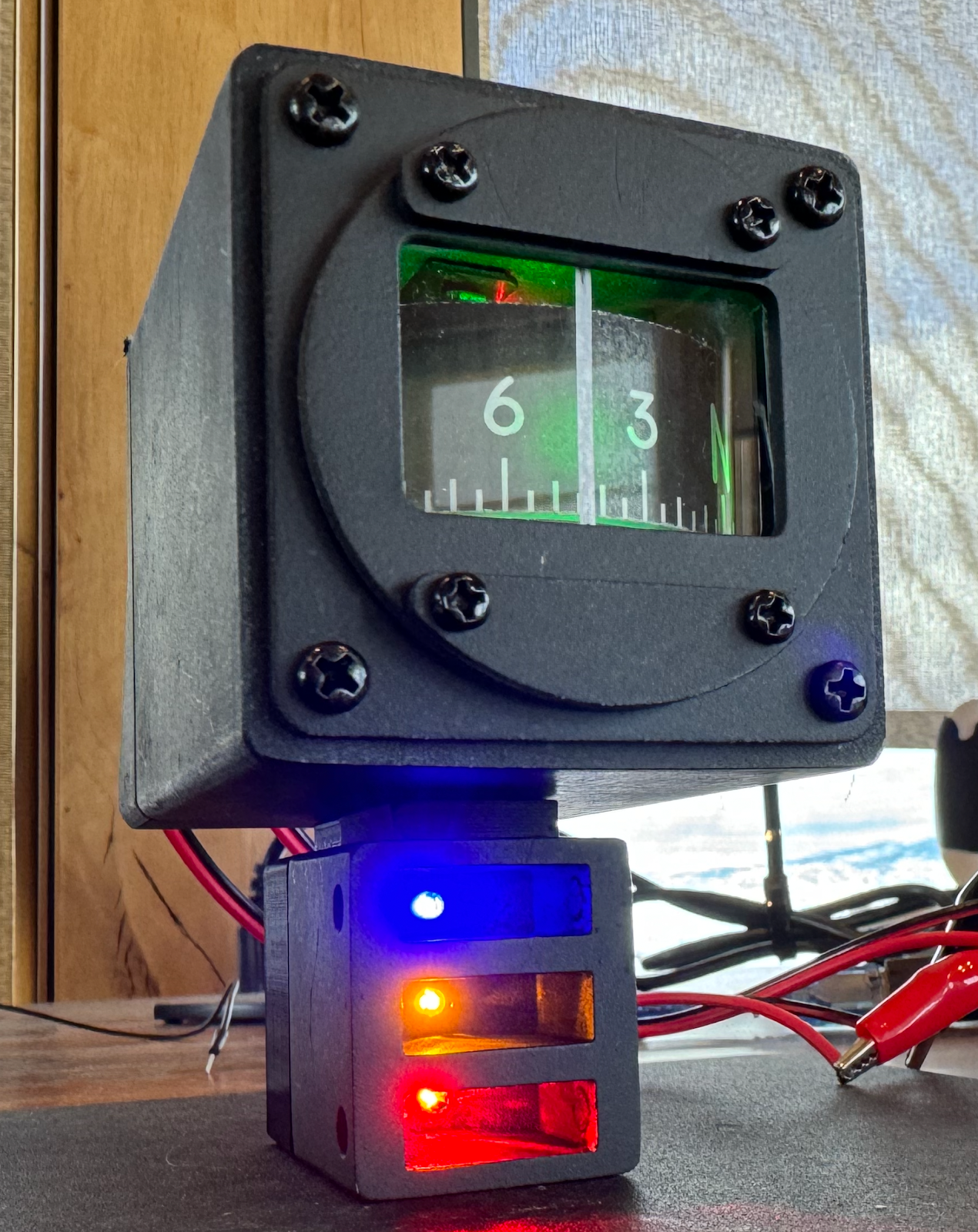
Got everything soldered together (after likely damaging one EasyDriver and moving to a backup) and squeezed it into the case. At first I thought the compass wheel was much too high but then I realized the front bezel was installed upside down. Used an Exacto knife to cut a piece of acrylic for the front glass and put a small vertical sticker on it to act as the reference line. Not super pretty but works ok until I can cut with a laser instead (maybe an xTool). Getting everything to fit was trickier than I expected, but it all worked out without too much rework required. I used some 5.5mm x 2.1mm plugs for the 12v power plugs (tip/center was positive). For the aerial refueling LEDs I used some more LEDs that have resistors built-in. They are made for 12v so will likely bit a little dim since I am powering them off the digital out 5v pins from the Nano. Don't have a way to make the lens for those yet so will wait to see if that is the case. ...